Engineering
Air Standard Cycles in Thermal Engineering
A comprehensive guide to air-standard cycles, covering thermodynamic classification, ideal assumptions, and the mechanics of Otto, Diesel, and Dual cycles.
May 4, 202618 min listen5 chapters
What you'll learn
- Understand the core assumptions of air-standard thermodynamic models
- Differentiate between power, gas, and combustion cycles
- Analyze the four stages of Otto, Diesel, and Dual cycles
- Compare thermal efficiency based on compression and cut-off ratios
Introduction to Air-Standard Cycles
note
Air-standard cycle
A simplified thermodynamic model of an engine cycle where:
- the working fluid is treated as air
- air behaves as an ideal gas
- the cycle is analyzed as closed and reversible in the idealized sense
Used to study real engines without all the messy details.
diagram
note
Thermodynamic cycle classification
1) By purpose
- Power cycles: produce net work
- Refrigeration / heat pump cycles: consume work to move heat
2) By working fluid
- Gas cycles: working fluid remains a gas
- Vapor cycles: working fluid undergoes phase change
diagram
equation
System Boundaries and Assumptions
note
Open vs Closed cycle
- Closed cycle: same mass of working fluid remains inside the system
- Open cycle: mass enters and leaves the system boundary
Key idea
- Closed → analyze as a fixed mass system
- Open → analyze as a control volume
diagram
note
Air-standard assumptions
- The working fluid is air.
- Air behaves as an ideal/perfect gas.
- The cycle is internally reversible.
- Combustion is replaced by an external heat-addition process.
- Exhaust is replaced by an external heat-rejection process.
These assumptions make the cycle easy to analyze.
equation
note
Perfect gas / ideal gas
For air-standard analysis, perfect gas usually means:
- equation of state: (PV = nRT)
- properties depend mainly on temperature
- specific heats are often treated as constant in the simplest model
equation
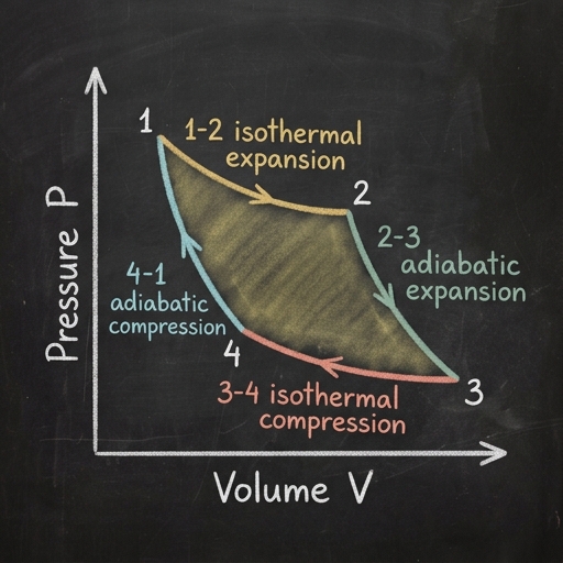
The Carnot Cycle Reference
illustration
note
Carnot cycle stages
- Isothermal expansion at high temperature (T_H)
- Adiabatic expansion
- Isothermal compression at low temperature (T_L)
- Adiabatic compression
Meaning
- Isothermal: heat transfer occurs to keep temperature constant
- Adiabatic: no heat transfer
equation
note
Carnot cycle: four steps in detail
1) Isothermal expansion at (T_H)
- Gas expands
- It does work on the surroundings
- Heat enters to keep temperature constant
2) Adiabatic expansion
- Gas keeps expanding
- No heat transfer
- Temperature drops from (T_H) to (T_L)
3) Isothermal compression at (T_L)
- Surroundings compress the gas
- Heat leaves the gas
- Temperature stays constant
4) Adiabatic compression
- Gas is compressed with no heat transfer
- Temperature rises from (T_L) back to (T_H)
Result
- The cycle returns to its initial state
- Net work equals the area enclosed by the P–V loop
equation
note
State-point notation
- (U_1, U_2, U_3, U_4): internal energy at states 1, 2, 3, 4
- (P_1, P_2, P_3, P_4): pressure at states 1, 2, 3, 4
- (T_1, T_2, T_3, T_4): temperature at states 1, 2, 3, 4
- (W_t): total work output of the cycle
Otto Cycle Analysis
note
Ideal cycle processes on a P–V diagram
Common process types
- Isothermal: temperature constant
- Adiabatic: no heat transfer
- Isobaric: pressure constant
- Isochoric: volume constant
For many air-standard cycles
- Compression is often adiabatic
- Expansion is often adiabatic
- Heat addition/rejection can be isochoric or isobaric depending on the cycle
diagram
equation
diagram
equation
diagram
note
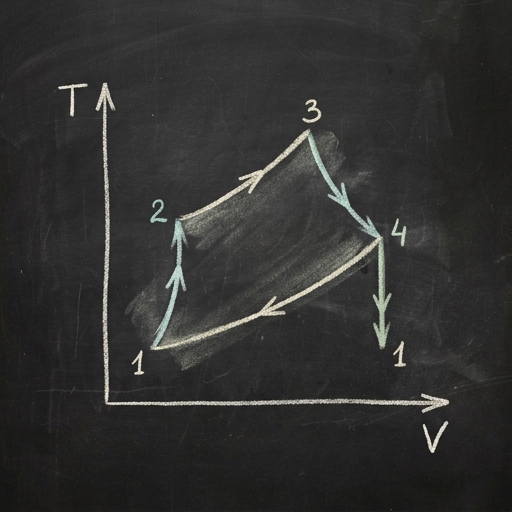
Otto cycle on a P–V diagram
- 1→2: compression curve rises as volume decreases
- 2→3: vertical line up, because volume is constant
- 3→4: expansion curve falls as volume increases
- 4→1: vertical line down, because volume is constant
equation
equation
equation
equation
Diesel and Dual Cycle Comparison
diagram
equation
note
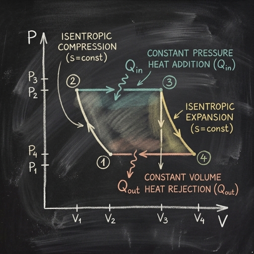
Diesel cycle key ratios
- Compression ratio: (r = \dfrac{V_1}{V_2})
- Cut-off ratio: (\rho = \dfrac{V_3}{V_2})
- (\gamma = \dfrac{c_p}{c_v})
illustration
diagram
note
Diesel cycle on a P–V diagram
- 1→2: compression curve goes up-left
- 2→3: constant-pressure line goes to the right
- 3→4: expansion curve goes down-right
- 4→1: constant-volume line goes straight down
illustration
note
Diesel cycle working
-
Compression stroke (1→2)
- Air is compressed strongly
- Pressure and temperature rise
- Idealized as isentropic
-
Heat addition at constant pressure (2→3)
- Fuel is injected and burns
- Pressure stays constant
- Volume increases
- This is the cut-off period
-
Expansion stroke (3→4)
- Hot gases expand and do work on the piston
- Pressure and temperature fall
- Idealized as isentropic
-
Heat rejection at constant volume (4→1)
- Exhaust heat is rejected in the ideal model
- Volume stays fixed
- Pressure drops back to the start state
equation
diagram
note
Dual cycle
- 1→2: isentropic compression
- 2→3: constant-volume heat addition
- 3→4: constant-pressure heat addition
- 4→5: isentropic expansion
- 5→1: constant-volume heat rejection
equation
equation
equation
note
Otto vs Diesel vs Dual
| Cycle | Heat addition | Compression | Expansion |
|---|---|---|---|
| Otto | Constant volume | Isentropic | Isentropic |
| Diesel | Constant pressure | Isentropic | Isentropic |
| Dual | Both constant volume and constant pressure | Isentropic | Isentropic |
Exam cue
- Otto: spark ignition
- Diesel: compression ignition
- Dual: mixed ideal model
diagram
equation
equation
note
Efficiency trend
- Higher compression ratio generally means higher efficiency
- For the same compression ratio, Otto is usually more efficient than Diesel
- Dual lies between Otto and Diesel depending on how heat is split
diagram
note
Same compression ratio, same heat input
- Otto: heat added at constant volume → larger pressure rise
- Diesel: heat added at constant pressure → volume rises during heat addition
- Therefore, for the same (r) and same (Q_{in}), Otto usually has higher thermal efficiency
Keep going with Slate
Pick up where this left off in your own voice session.
Built with Slate